As the "heart" of electronic devices, crystal oscillators primarily generate stable reference clock signals. However, their native output frequency often fails to directly meet the requirements of various system modules—some require high-frequency clocks for faster processing speeds, while others need low-frequency clocks to reduce power consumption and achieve precise timing. In such cases, frequency division technology becomes crucial for aligning the oscillator's reference frequency with system demands. By employing digital circuits to reduce the oscillator's original frequency by a fixed ratio, a low-frequency clock signal that meets the requirements is produced.
The fundamental principle of crystal frequency division involves applying digital frequency division circuits (composed of components such as flip-flops, counters, and phase-locked loops) to perform logical operations of "counting-flipping-output" on the original clock signal generated by the crystal oscillator. This process reduces high-frequency signals to lower frequencies by integer multiples (or precise decimal fractions), with the core mechanism adhering to the following formula:
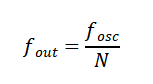
Where: is the original output frequency of the crystal oscillator (reference frequency); is the output frequency after frequency division; is the frequency division factor (a positive integer or precise decimal number, determined by the design of the frequency division circuit).
The core logic of frequency division is "periodic counting": for every N received original clock pulses, the frequency division circuit outputs one pulse, achieving a proportional frequency reduction. Depending on the implementation method, frequency division circuits are primarily divided into two categories:
1. Programmable frequency division: By integrating a Phase-Locked Loop (PLL) with digital programming circuits, the division factor can be adjusted via software or hardware configuration, supporting multi-frequency output with high flexibility, making it ideal for complex systems.
2. Fixed hardware frequency division: Composed of hardware components such as flip-flops and counters to form a fixed logic circuit with an immutable division factor (e.g., binary division or multi-stage cascaded division). It features a simple structure, high stability, and no additional errors.
Key considerations: Frequency division only alters the clock signal's frequency (reducing frequency or extending period) without affecting signal stability. The original frequency precision (e.g., temperature offset ±25ppm) and stability of the crystal oscillator are fully preserved in the output signal after frequency division, which constitutes the fundamental prerequisite for high-precision frequency division.
Typical Case 1: Frequency Division of Programmable Crystal Oscillator
Programmable oscillators (model numbers YSO690PR, YSO212PU, YSO250PT) are highly flexible frequency devices featuring a core architecture combining fixed fundamental frequency crystals, PLL frequency multiplication, and programmable frequency division. With factory-programmable frequency division parameters, they deliver wide frequency output ranges (up to 2100MHz) and short delivery cycles. Their customizable frequency points and easy debugging capabilities make them widely adopted in industrial control systems, medical electronics, communication equipment, and other fields requiring high frequency flexibility and delivery efficiency.
Typical Case 2: Frequency Division of an Active 32.768kHz Crystal Oscillator (High-Precision Timing Application)
32.768kHz is the most critical frequency in RTC systems, widely used in timing circuits where the core requirement is frequency division to 1Hz second pulses for precise timing. High-precision active 32.768kHz crystal oscillators available on the market (with temperature deviation of ±25ppm) all adopt a design featuring "AT-cut MHz-level base frequency chips + dedicated digital frequency divider ICs (including oscillator circuits, shaping circuits, and fixed dividers)." This architecture achieves accurate frequency division from MHz-level base frequencies to 32.768kHz, then outputs standard square waves (CMOS level).
Why not directly use AT-cut wafers for a 32.768 kHz fundamental frequency? The reason lies in the inverse proportionality between the frequency of AT-cut crystals and wafer thickness. A wafer thickness corresponding to a 32.768 kHz fundamental frequency reaches several millimeters, resulting in poor mechanical stability and temperature drift exceeding ±25 ppm. In contrast, MHz-level AT-cut wafers (e.g., 8 MHz) have a thickness of only tens of micrometers, featuring mature manufacturing processes and controllable precision. After frequency division, their high-precision characteristics can be perfectly inherited.
Divide 32.768kHz to 1Hz (RTC core requirement)
The unique value of 32.768kHz enables precise timing through a 15-stage binocular frequency divider circuit, which further reduces the frequency to 1Hz per second pulses.
Each stage employs a T flip-flop for binning, where the output level inverts once per input clock rising edge to achieve frequency division by 2. After 15 cascaded stages, the total binning factor is, resulting in a final output of a 1 Hz square wave (period 1 s).
Typical application: RTC chips (e.g., YSN8563, YSN8900) feature an integrated 15-stage binary frequency divider circuit that generates 1Hz second pulses for driving time counters, enabling functions such as calendar, alarm, and counting.