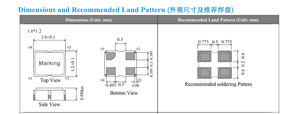
Active crystal oscillator circuit diagram and pinoutA typical active crystal oscillator has four pins. The missing corner is called pin 1 (PIN 1), and going counterclockwise (pins pointing downward), they are pins 2, 3, and 4.
Pin 1 is tri-state/no connection.
Pin 2 is grounded.
Pin 3 is connected to the output signal.
Pin 4 is connected to the power supply voltage (VDD).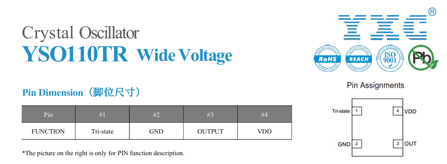
However, it should be noted that the connection method varies depending on the active crystal oscillator model. If the crystal oscillator's Pin 1 has an E/D enable function or a standby function, grounding it will prevent the crystal oscillator from outputting a frequency signal. Therefore, please carefully read the relevant instructions in the data sheet before wiring to avoid incorrect wiring that may cause the active crystal oscillator to malfunction. As shown in the figure below: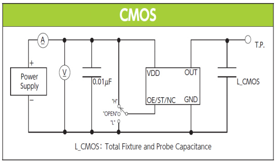
An active crystal oscillator contains a quartz crystal, an oscillator IC, matching capacitors, and other peripheral circuits. It offers high precision and stable output signals, requiring no external circuit design and is easy to use. However, it does require a power supply. When using an active crystal oscillator, special attention must be paid to ensuring that the power supply is regulated, the power leads are as short as possible, and the system's GND is shared with any chips using the crystal oscillator signal.


