一、What is a BMS?
BMS stands for Battery Management System. It is a device that monitors the status of energy storage batteries. Typically, a BMS is a circuit board or hardware box.
1. Real-time Monitoring
Voltage Monitoring: Measure the total voltage and the voltage of each cell or module.
Current Monitoring: Measure the total charge and discharge current.
Temperature Monitoring: Detect temperature changes at various points within the battery pack using temperature sensors.
2. State Estimation
SOC (State of Charge) Estimation of Remaining Capacity: Estimates the remaining charge in the battery pack using the ampere-hour integration method and the open-circuit voltage method.
SOH (State of Health) Estimation of State of Health: Analyzes the battery's internal resistance growth, full-charge capacity decay, and the number of charge and discharge cycles to comprehensively estimate the battery's aging.
SOP (State of Power) Estimation of Available Power: Estimates the maximum discharge power the battery can provide and the maximum charge power it can accept in a short period of time (such as a few seconds or tens of seconds).
SOE (State of Energy) Estimation of Remaining Energy: Estimates the battery's currently available energy (in kWh), which is more direct for predicting range.
3. Protection - Safety Management
When an abnormal or dangerous condition is detected, the BMS takes immediate action, shutting off power.
Overvoltage Protection: When any cell voltage exceeds the upper safety limit, the charging circuit is shut off to prevent overcharging.
Undervoltage Protection: When any cell voltage falls below the lower safety limit, the discharge circuit is shut off to prevent overdischarge.
Overcurrent Protection: When the charge or discharge current is excessive, the circuit is shut off to prevent short circuits or overloads.
Overtemperature Protection: When the battery temperature exceeds the safety threshold, the power is reduced or the circuit is shut off.
Short-Circuit Protection: In the event of a severe short circuit, the circuit is shut off at the fastest speed (microseconds).
Insulation Monitoring: Monitors the insulation resistance between the high-voltage system and the vehicle chassis to prevent leakage risks.
Fault Diagnosis and Recording: The BMS records all fault information and generates fault codes to provide a basis for subsequent repairs.
4. Controls the balancing circuit to maintain consistent charge levels across all cells, extending battery life.
5. Key events are time-stamped and stored in flash memory for fault tracing and warranty analysis.
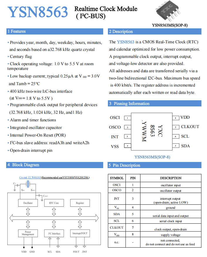
二、Why is RTC required in BMS? Taking YSN8563MS as an example
The core purpose of BMS equipped with RTC (real-time clock chip, such as the common YSN8563) is to ensure that the system still has an absolute, traceable, and low-power "time coordinate" in the "power-off + sleep" state.
(1) Timed wake-up from sleep mode - turning "constant standby" into "intermittent physical examination"
When the vehicle is turned off, the main MCU is powered off and the RTC runs on the 0.3–0.5 µA of the button battery; at the preset time (such as every 4 hours or 2 am every day), an interrupt signal is output to wake the BMS from Deep Sleep and perform battery cell voltage/temperature inspection.
(2) SOC static correction
The ampere-hour integration method will drift over a long period of time and must be corrected using the open circuit voltage method; the open circuit voltage method requires that the battery be left at rest for ≥2 hours and the "actual rest time" is known. The RTC keeps timing. After the system restarts, it will compare the last shutdown time to calculate the actual idle time. When the idle time is ≥ 2 hours, the open circuit voltage method is triggered and the system goes into sleep again after completion, which saves power and avoids missed detection.
(3) Accurate fault timing
The national standard GB 38031-2020 and accident identification require that key events have a time stamp with 1 second accuracy. The RTC keeps running when the system is powered off, providing absolute calendar time for fault codes (DTC), overcharge, over-discharge, thermal runaway log, and EDR collision record, avoiding the invalidation of evidence with "only serial number but no time".
(4) Temperature sampling and time stamping
High-temperature calendar aging and cycle aging are closely related to temperature and time. The RTC can accurately time stamp the temperature sampling, allowing the BMS to accumulate the high-temperature exposure time, number of cycles/intervals, and thus dynamically adjust the maximum charging current, warn of SOH diving, and improve quality assurance confidence.
三、Why is an RTC installed separately instead of the RTC built into the MCU?
Higher Accuracy: Dedicated RTC chips (such as the 8563) typically use an external 32.768kHz crystal oscillator, offering far greater time accuracy than most MCU built-in RTCs.
Lower Power Consumption: In sleep mode, dedicated RTCs can consume microamperes or even nanoamperes, lower than the power consumption of the entire MCU during sleep, and support extended BMS sleep.
Greater Reliability: As an independent chip, it is unaffected by MCU main program crashes or resets. Even if the vehicle system is restarted, time information is not lost (powered by a backup battery or supercapacitor).
Functional Integration: The RTC clock chip (YSN8563) integrates timers, alarms, clock outputs, and precise timestamps, facilitating system design and enabling precise fault location.