In the crystal oscillator circuit, two resistors are generally designed. One is connected across the two ends of the crystal oscillator, called the feedback resistor Rf; the other is connected to the output end of the IC, called the current limiting resistor RD; the capacitor connected to the crystal is called the load matching capacitor. By adjusting the capacitance, the frequency of the oscillation circuit can be changed, and these waveform frequency tests can be observed.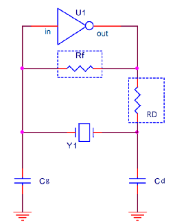
1、Feedback resistor Rf:
The main chip connected in series with the crystal is a linear operational amplifier, which outputs the input in reverse 180 degrees. The load capacitor at the crystal oscillator provides another 180 degrees of phase shift. The phase shift of the entire loop is 360 degrees, which meets the phase condition of the oscillation. At the same time, the closed-loop gain is required to be greater than or equal to 1, so that the crystal oscillator can work normally.
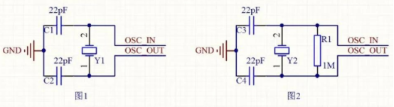
In actual product design, the circuit of the crystal oscillator part will have the following two circuits. In the circuit of Figure 1, there is no 1M feedback resistor. In the circuit of Figure 2, the crystal oscillator will be connected in parallel with a 1M resistor.
The role of the feedback resistor is summarized in 3 points:
1) Cooperate with the internal circuit of the IC to form negative feedback and phase shift, so that the amplifier works in the linear region.
2) Stabilize the output amplitude and phase.
3) Increase the stability of the oscillation circuit. For example, when the temperature changes, the resistance value can be adjusted to maintain the stability of the oscillation frequency.
2、Current-limiting resistor RD:
The role of this resistor is to limit the driving capability of the IC and form a low-pass filter with Cd to ensure that the starting point of the oscillator is at the fundamental frequency, rather than at other high-order harmonic frequencies (avoiding 3rd, 5th, and 7th harmonic frequencies). If the power consumption of the crystal oscillator exceeds the given value of the crystal oscillator manufacturer, the external resistor Rd is necessary to prevent the crystal oscillator from being overdriven. If the power consumption of the crystal oscillator is less than the given value of the crystal oscillator manufacturer, it is not recommended to use Rd, and 0Ω can be preset. As shown in Figure 3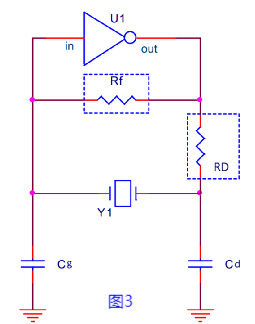
The estimation of the Rd value can be achieved by considering the voltage divider Rd/Cd of Rd and Cd (note that Rd and Cd form a voltage divider/filter, considering that the passband width should not be less than the oscillator frequency), then the value of Rd is equal to the reactance of Cd: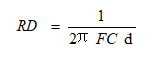
The role of the current-limiting resistor is summarized in 3 points:
1) Suppress EMI. We can improve EMI by adjusting the resistance value.
2) Prevent the crystal oscillator from being overdriven and protect the stability of the crystal oscillator's electrical performance.
3) Use it as a TP point to facilitate waveform measurement.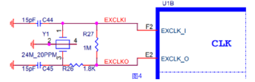
Finally, I would like to remind you that if the IC part already contains a feedback resistor, then the external crystal oscillator circuit does not need to add a feedback resistor. So remember to read the IC manual carefully. If the crystal oscillator circuit does not have an overdrive problem, then this current limiting resistor can also be omitted.