As communication speeds increase, many differential transmission interfaces have emerged to improve performance, reduce power consumption and cost. Early technologies, such as emitter-coupled logic (ECL), used a constant negative power supply to improve noise suppression at the time. With the development of positive voltage supply technology, such as TTL and CMOS technology, the original technical advantages began to disappear because they required some -5.2V or -4.5V levels.
In this context, ECL transformed into positive/pseduo emitter-coupled logic (PECL), simplifying board-level wiring and abandoning negative level power supply. PECL requires a voltage swing of 800mV and uses a voltage of 5V to ground. LVPECL is similar to PECL, which is 3.3V power supply, and has advantages in power consumption.
As more and more designs adopt CMOS-based technology, new high-speed drive circuits have begun to emerge, such as current mode logic (CML), votage mode logic (VML), and low-voltage differential signaling (LVDS). These different interfaces require different voltage swings, and the connection between them in a system also requires different circuits.
· Conversion reasons
1. Level characteristics difference
a) LVPECL level has a large differential swing (typical value of about 800mV), a high common mode voltage (about 1.3V-1.9V), and requires external termination resistor matching; while LVDS has a small differential swing (350mV), a low common mode voltage (about 1.2V), and the LVDS receiver has a built-in termination resistor.
b) Direct connection may cause the common mode voltage of the LVDS receiver to exceed the range or the signal amplitude to be insufficient.
2. Application scenario requirements
a) LVPECL is often used in high-speed clock or data transmission scenarios (such as FPGA output), while LVDS is more suitable for long-distance or low-power designs due to its low power consumption characteristics.
b) Level conversion is required when interfaces between different devices are incompatible (e.g. FPGA outputs LVPECL, but the receiver only supports LVDS)
· Conversion method
1. DC coupling
The DC coupling structure from LVPECL to LVDS requires a resistor network, as shown in Figure 1. There are several points that must be considered when designing the network: First, we know that when the load is 50Ω connected to Vcc-2V, the output performance of LVPECL is optimal, so we consider that the resistor network should be equivalent to the optimal load; then we also need to consider that the attenuation introduced by the resistor network should not be too large, and the LVPECL output signal can still fall within the effective input range of LVDS after attenuation. Note that the input differential impedance of LVDS is 100Ω, or 50Ω for each single-ended to virtual ground. This impedance does not provide a DC path, which means that the LVDS input AC impedance is not equal to the DC impedance. After calculation, the resistance values are: R1=182Ω, R2=48Ω, R3=48Ω. The resistors are placed close to the receiving side.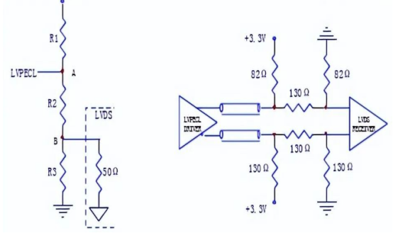
(a) Equivalent circuit (b) Connection from LVPECL to LVDS Figure 1.1 DC coupling structure from LVPECL to LVDS
2. AC coupling
The AC coupling structure from LVPECL to LVDS is shown in Figure 2. A DC bias resistor (142Ω to 200Ω) is required from the output of LVPECL to ground, and a 50Ω resistor must be connected in series on the signal channel to provide a certain attenuation. A 5KΩ resistor is required from the input of LVDS to ground to provide a common-mode voltage of approximately 0.86V.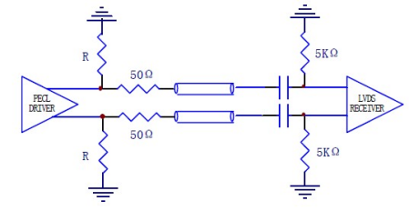
Figure 1.2 AC coupling structure from LVPECL to LVDS
In terms of signal conversion, the conversion from LVPECL to LVDS requires consideration of the placement of attenuation resistors and AC coupling capacitors, as well as the re-biasing of the LVDS receiver. Conversely, the conversion from LVDS to LVPECL also requires appropriate circuit design and component selection.
LVDS and LVPECL each have their own characteristics and application scenarios. LVDS is suitable for intra-board signal transmission and high-speed changing signal transmission, while LVPECL is suitable for backplane transmission and long cable transmission, which require strong driving capability and high transmission speed. However, although the conversion from LVPECL to LVDS can be achieved through circuit design, we recommend that customers try to choose differential transmission interfaces with the same type of waveform, after all, circuit conversion will have many other uncertain effects.